

Introduction to Geometric Calibration
Geometric calibration refers to a camera's ability to convert a 2D image into a 3D representation of the real-world field of view. In photogrammetry, distances are measured in images. In conventional photography, distortion is measured and compensated in the image processing pipeline. In automotive applications, distances to objects are calculated from the measured geometric characteristics of the camera or a stereo camera pair.
Why is geometric calibration essential?
As stated above, geometric calibration is vital for systems that rely on detecting and accurately mapping 3D objects in a moving scene. After proper geometric calibration, the camera system will more precisely measure distances and identify objects in a scene. The system will also better adjust for high distortion levels and accurately align stereo camera pairs.
Geometrically calibrated camera systems are used across various industries, but they are particularly important in the automotive industry. Automotive systems, in particular, need to map distances to objects to improve performance and safety.
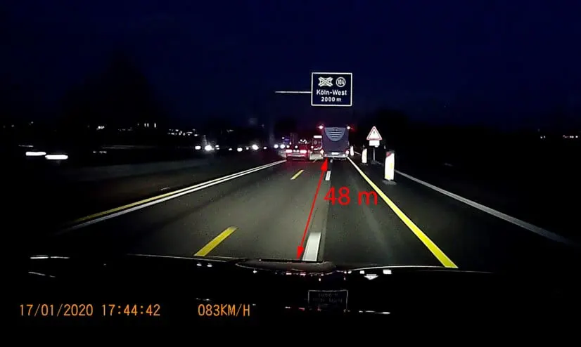
Geometric calibration test methods
There are several current geometric calibration methods, most notably test-chart methods. These charts use standard patterns (e.g., crosses, dots, or checkerboards) to determine the distortion over the imaging field. The chart must match the camera’s field of view; i.e., the wider the field of view, the larger the chart must be. Automotive cameras often use wide-angle lenses and thus require large-format charts for proper geometric calibration.
More compact test methods require relay lenses. Using relay lenses allows measurement from infinity, but they also introduce distortion and must be characterized before geometric calibration. Both methods allow distortion measurements and inner orientation, but neither can measure outer orientation.
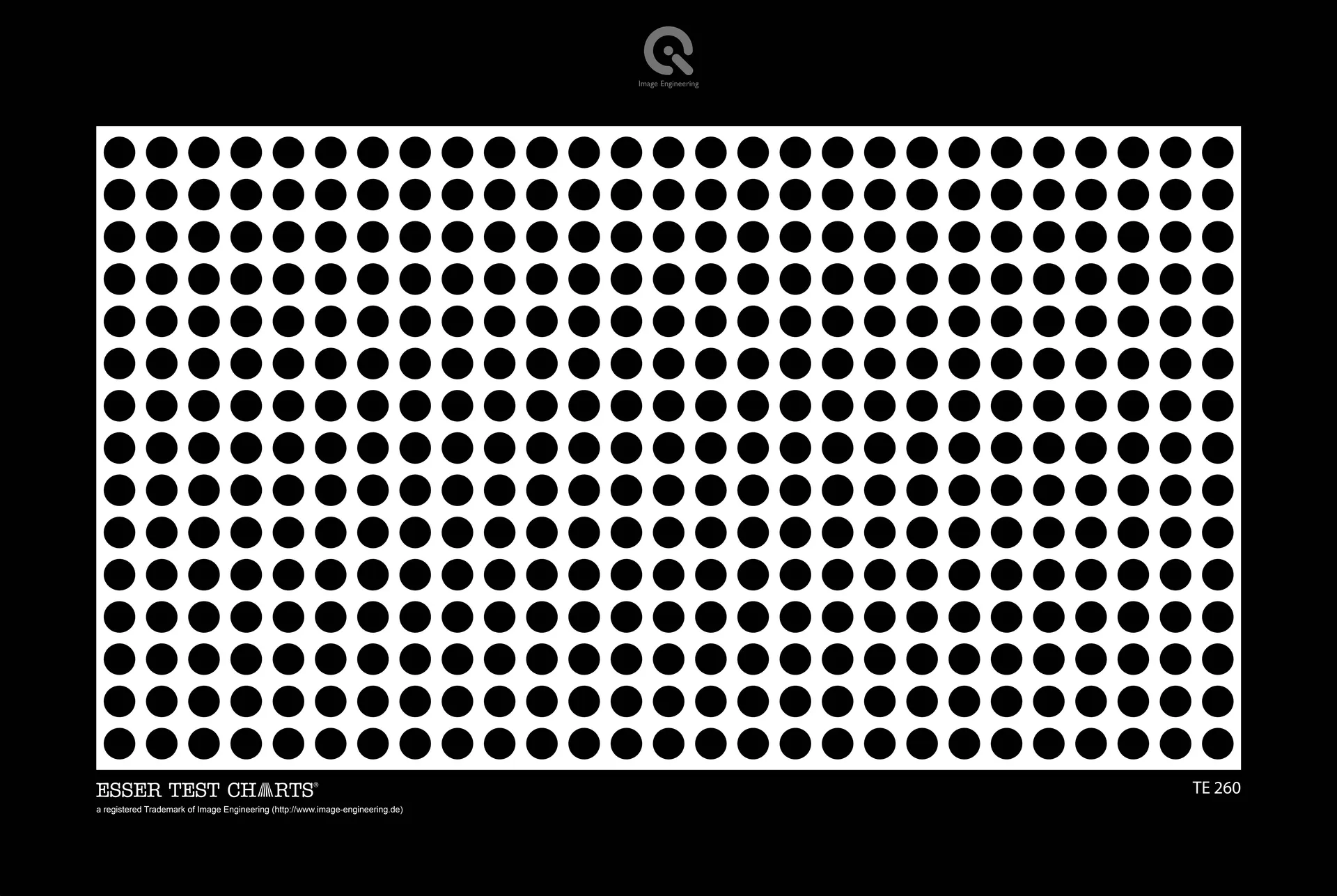
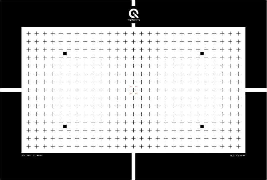
A new geometric calibration test method
As the need for geometric camera calibration continues to expand in the automotive industry, demand for more robust test methods is growing rapidly. With that in mind, we set out to develop a new solution that would advance geometric camera calibration to a new level.
When designing new geometric calibration technology, we sought to address the issues that arise with traditional methods, and as a result, the GEOCAL was born. GEOCAL technology uses a beam expanded laser in combination with a diffractive optical element (DOE).
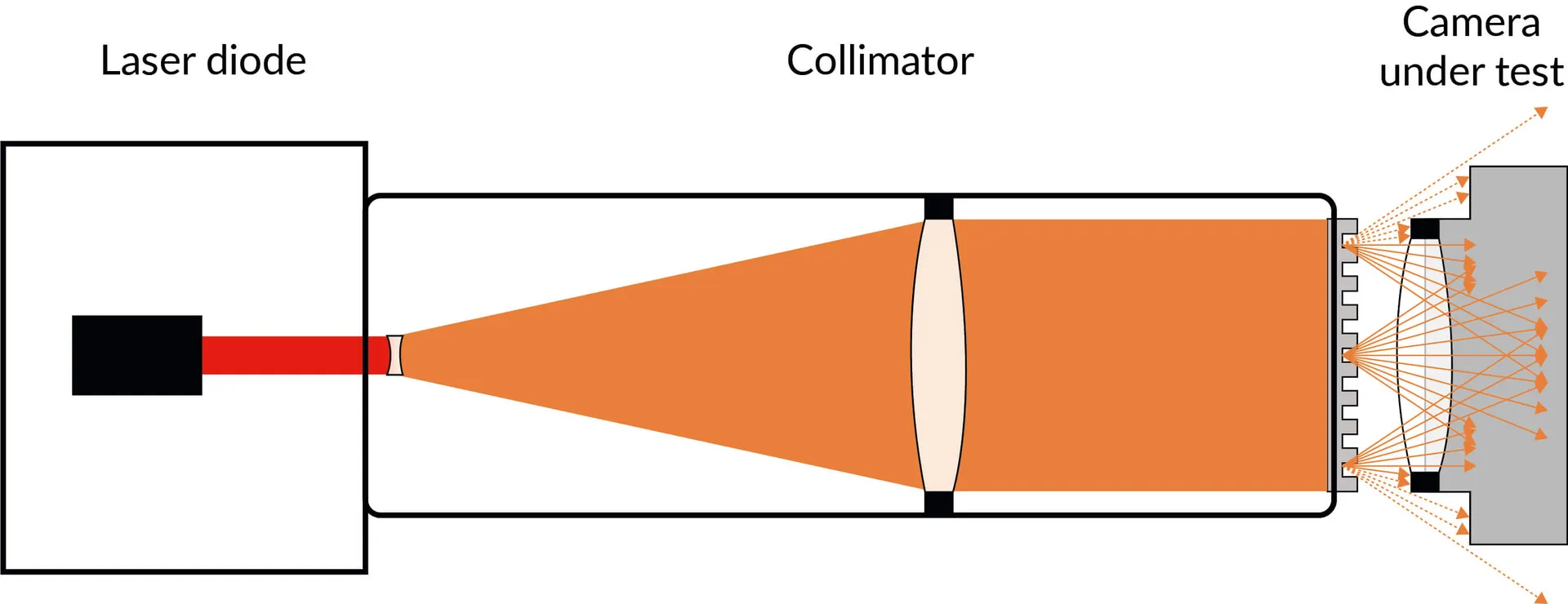
GEOCAL Technology
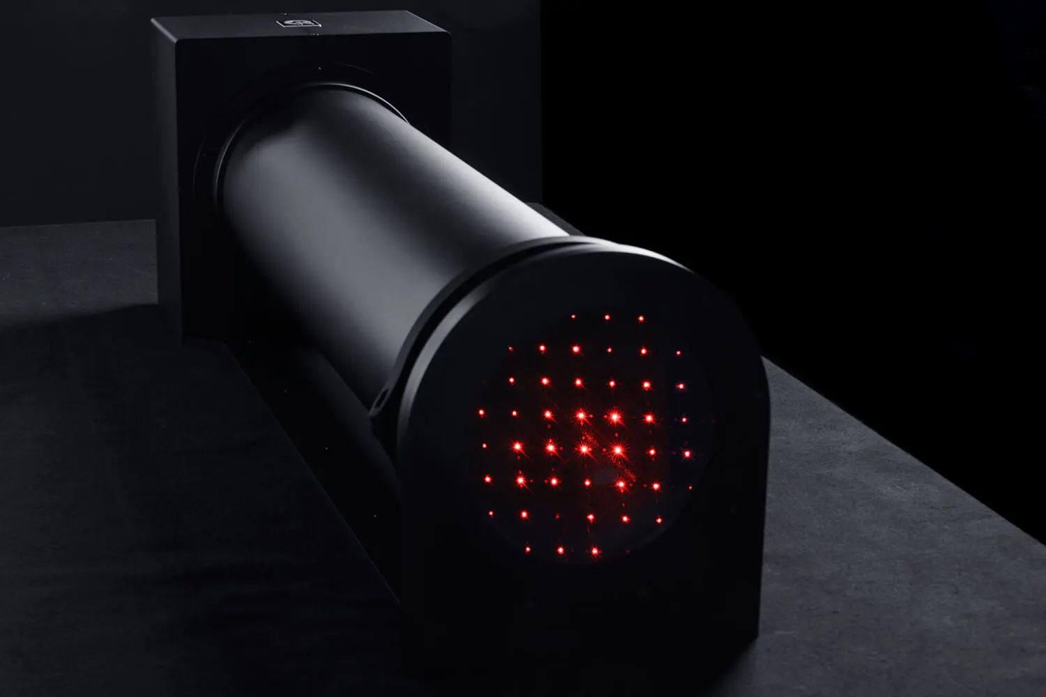
With GEOCAL technology, you can generate a grid of light spots emanating from infinity, and the camera's position is translation-invariant (to a certain extent). This method distinguishes itself from traditional methods because it requires no relay lens to calibrate at infinity. Calibration of a large-field-of-view camera is possible, as is stereo camera adjustment.
This technology creates a much more flexible solution than traditional methods that rely on test charts with regular patterns (these patterns also need to be scaled depending on the field of view and the intended object distance) and excess products (relay lenses) when calibrating from infinity.
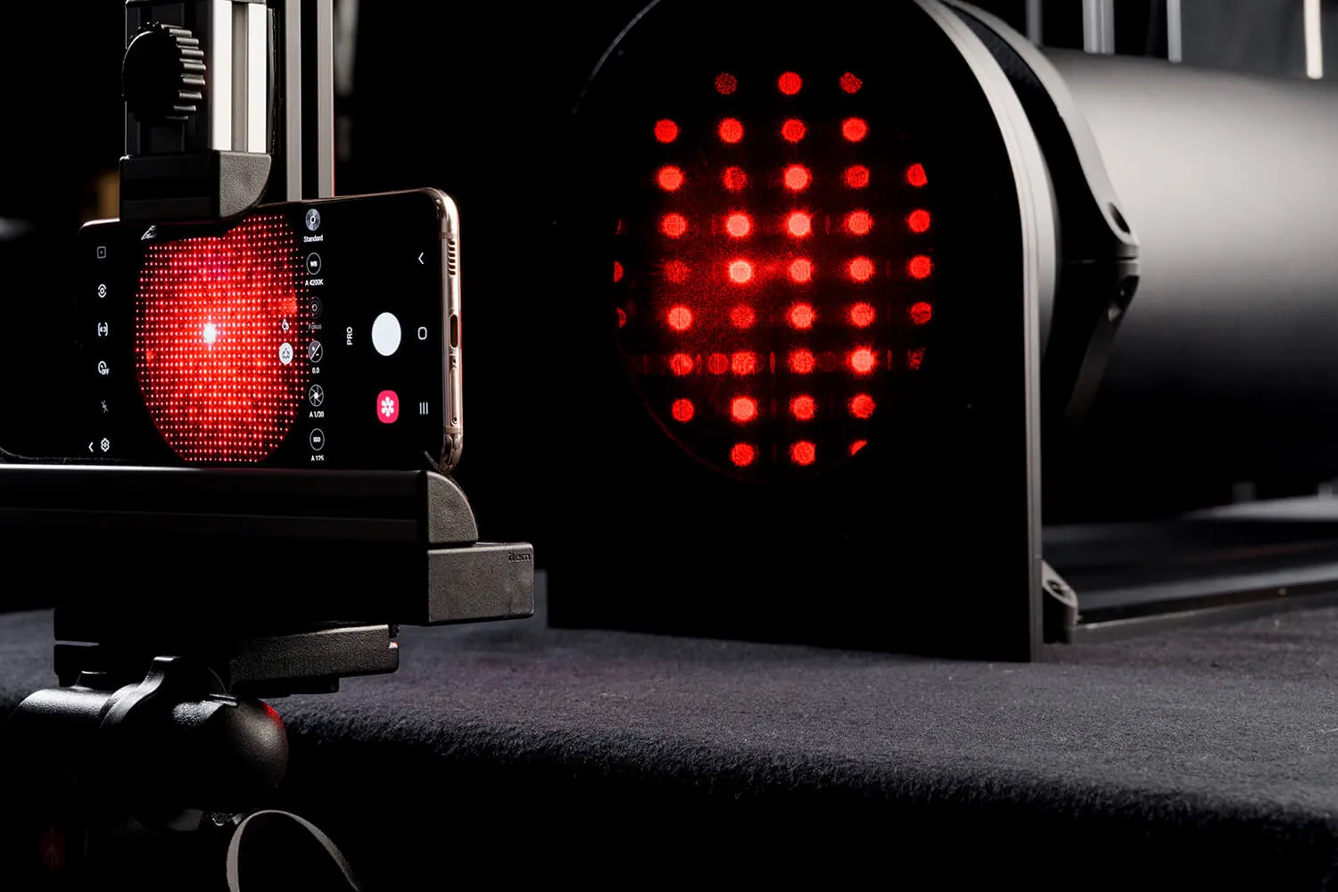
The GEOCAL Device
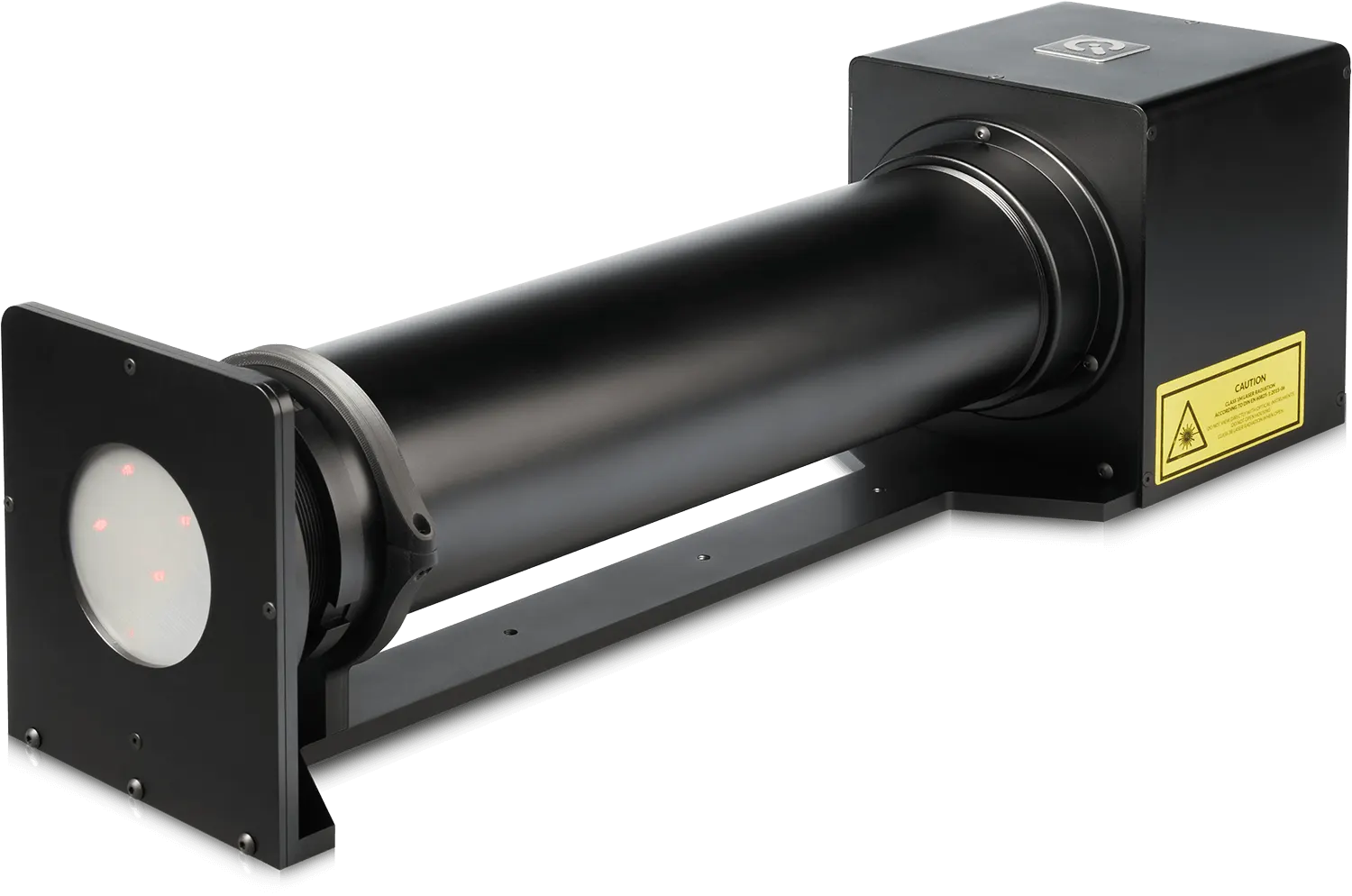
Using this new technology, our development team created the GEOCAL device, which combines a beam-expanded laser with a diffractive optical element to deliver a modern solution for geometric camera calibration. One of the main benefits of the GEOCAL over other methods is its compact design. Such a design creates more opportunities for integration into test labs of any size, without the need for relay lenses.
GEOCAL has a standalone software solution with a GUI for evaluating test results, and we are currently implementing it in the iQ-Analyzer-X.
See the GEOCAL product page for more details.
Want to learn more about geoemetric calibration?
Contact us to set up a training session with our engineers.