
Shading
color and lens shading correction | Introduction The term shading describes the light fall-off or color variation from the sensor center to the corners that do not originate from the captured scene. In other words, shading is a decrease of the image brightness from the center to the corners. Occasionally a variation of color over the imaging field can occur, particularly in cameras with a small sensor. Overall, shading influences image quality by creating unwanted dark or shaded edges. The background of shading When visualizing the shading of a camera system, it is easiest to capture a flat field image, a photograph of white paper with uniform illumination, or a photograph of a uniform diffuse light source such as the opening of an integrating sphere. The minimum shading an optical system has is that of the cosine law described in photometry. The optical design of the system can increase it. Vignetting can occur from the lens or other objects' physical limitations, such as improper lens filters or false lens hoods. Types of shading ISO 17957 breaks down shading into two main categories for measurement.1 The first category is luminance shading, which the standard defines as a variation of the luminance signal components within the image field. The second category is color shading, a variation of the chrominance signal components within the image field1. Luminance shading Luminance (also known as lightness) shading can be broken down into a few separate groups depending on where the shading occurs. Image 1: A typical test image showing the luminance shading from the center to the corners. Natural shading (cos4 law) Natural shading is when there is a light fall off from the center of the image to the corners. This type of shading is simply caused by geometry. Figure 1: The geometric explanation of natural shading. Figure 1 illustrates that the distance (D2) is D1 multiplied with the cosine of δ. It’s best to think of D2 and D1 in two dimensions (or rather areas instead of dimensions), and thus the energy moving from D2 towards the lens is the energy of D1 multiplied by (cos δ)2. We now also have the same situation on the lens's incident side as the energy transmitted by the lens is D2 multiplied by (cos δ)2. Both of these areas together result in the cos4 law: E(P2) = E(P1) * (cos δ)4 The maximum amount of natural shading in an image is determined by the camera's field of view. For example, a wide-angle image contains more natural shading than a telephoto image. Mechanical shading or vignetting Another part of luminance shading is known as mechanical shading or vignetting. The cause of this type of shading is the lens mount or other accessories such as the lens hood. It usually depends on the aperture or f-number, and smaller apertures usually show lower mechanical shading. Figure 2: The explanation for mechanical shading. Image 2: Mechanical shading with an open and closed aperture. Measuring luminance shading When measuring luminance shading, ISO 17957 differentiates between the CIELAB method of "lightness non-uniformity" and the X, Y, Z method of "luminance non-uniformity" using two related formulas. The standard describes the measurement in detail. Lightness shading: Luminance shading: With the measurement results of luminance shading, a polynomial fit can be calculated and used to brighten the corners to compensate for the shading. Thus, compensating for a moderate shading level can be done in the camera imaging piper or during raw image processing. Image 3: Luminance shading measurement results from the iQ-Analyzer. Color shading Color shading (or color non-uniformity) usually describes a shift in color from the center of the image to the corners. This type of shading typically occurs in images captured with a camera with a smaller sensor. Color shading has multiple causes, including the two most common types, pixel crosstalk off-axis, and the IR-cut filter transmission. Image 4: A color shading example showing a magenta spot in the center with green corners. Pixel crosstalk color shading Pixel crosstalk off-axis describes an increase in the spatial variation between (crosstalk) the pixels. Lenses that are not designed as near telecentric can often experience pixel crosstalk shading. Image 5: Light collected by the sensor varies with the angle of incidence due to pixel crosstalk. IR-cut filter The transmission of the IR-cut filter shifts towards a shorter wavelength as the angle of incidence increases. The IR-cut filter shift has a more substantial impact on the image if the light source contains a lot of IR radiance like natural sunlight or incandescent lights. Fluorescent tubes or LEDs do not display this phenomenon as often due to the lag of the IR content in their spectrums. Image 7: The test chart image on the left was taken with a light source that matches the D55 spectrum (sunlight) and shows significant colour shading along the edges. The same test chart image on the right, captured with a D55-simulating fluorescent tube (no IR), does not show colour shading. Measuring color shading ISO 17957 outlines two separate formulas for measuring color shading. The first formula describes the chrominance non-uniformity and focuses on the differences in the a* and b* channels. The second formula details the total color non-uniformity, which takes into account the lightness L*. Chrominance non-uniformity An analysis of the chrominance non-uniformity is performed by first calculating the overall average (a*) ̅ and (b*) ̅ for the entire image using the block average values: a^* (i) and b^* (i). m :number of measurement blocks Calculate the chrominance deviation of the i block with the following formula. The chrominance non-uniformity Dc is defined as the maximum deviation from the overall average of the following formula. Total color non-uniformity An analysis of total color non-uniformity begins by first calculating the overall maximums and minimums of L*(i), a*(i), and b*(i). Calculate the total color non-uniformity DTotal by the following formula. Conclusion Shading describes a decrease in image brightness from the center to the corners or a variation of color over the imaging field that often occurs in cameras with a small sensor. Shading, therefore, influences image quality by creating unwanted dark or shaded edges. When visualizing the shading of a camera system, it is easiest to capture a flat field image, a photograph of white paper with uniform illumination, or a photograph of a uniform diffuse light source such as the opening of an integrating sphere. When we test for camera shading in our test lab, we closely follow the methods presented in ISO 17957. We have found that using a matt diffuser chart provides us with the best results for an overall evaluation of shading.
Introduction
The term shading describes the light fall-off or color variation from the sensor center to the corners that do not originate from the captured scene. In other words, shading is a decrease of the image brightness from the center to the corners. Occasionally a variation of color over the imaging field can occur, particularly in cameras with a small sensor. Overall, shading influences image quality by creating unwanted dark or shaded edges.
The background of shading
When visualizing the shading of a camera system, it is easiest to capture a flat field image, a photograph of white paper with uniform illumination, or a photograph of a uniform diffuse light source such as the opening of an integrating sphere.
The minimum shading an optical system has is that of the cosine law described in photometry. The optical design of the system can increase it. Vignetting can occur from the lens or other objects' physical limitations, such as improper lens filters or false lens hoods.
Types of shading
ISO 17957 breaks down shading into two main categories for measurement.1 The first category is luminance shading, which the standard defines as a variation of the luminance signal components within the image field. The second category is color shading, a variation of the chrominance signal components within the image field1.
Luminance shading
Luminance (also known as lightness) shading can be broken down into a few separate groups depending on where the shading occurs.
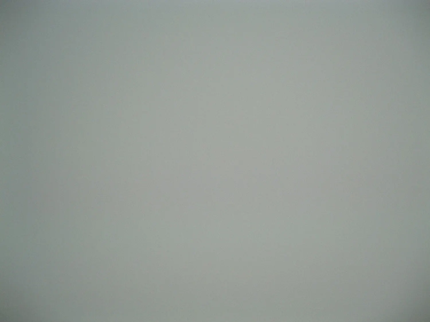
Image 1: A typical test image showing the luminance shading from the center to the corners.
Natural shading (cos4 law)
Natural shading is when there is a light fall off from the center of the image to the corners. This type of shading is simply caused by geometry.
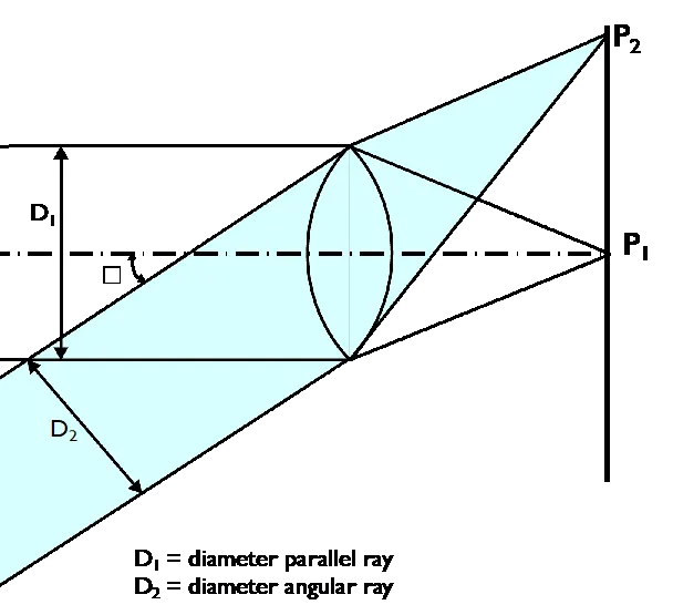
Figure 1: The geometric explanation of natural shading.
Figure 1 illustrates that the distance (D2) is D1 multiplied with the cosine of δ. It’s best to think of D2 and D1 in two dimensions (or rather areas instead of dimensions), and thus the energy moving from D2 towards the lens is the energy of D1 multiplied by (cos δ)2. We now also have the same situation on the lens's incident side as the energy transmitted by the lens is D2 multiplied by (cos δ)2.
Both of these areas together result in the cos4 law:
E(P2) = E(P1) * (cos δ)4
The maximum amount of natural shading in an image is determined by the camera's field of view. For example, a wide-angle image contains more natural shading than a telephoto image.
Mechanical shading or vignetting
Another part of luminance shading is known as mechanical shading or vignetting. The cause of this type of shading is the lens mount or other accessories such as the lens hood. It usually depends on the aperture or f-number, and smaller apertures usually show lower mechanical shading.
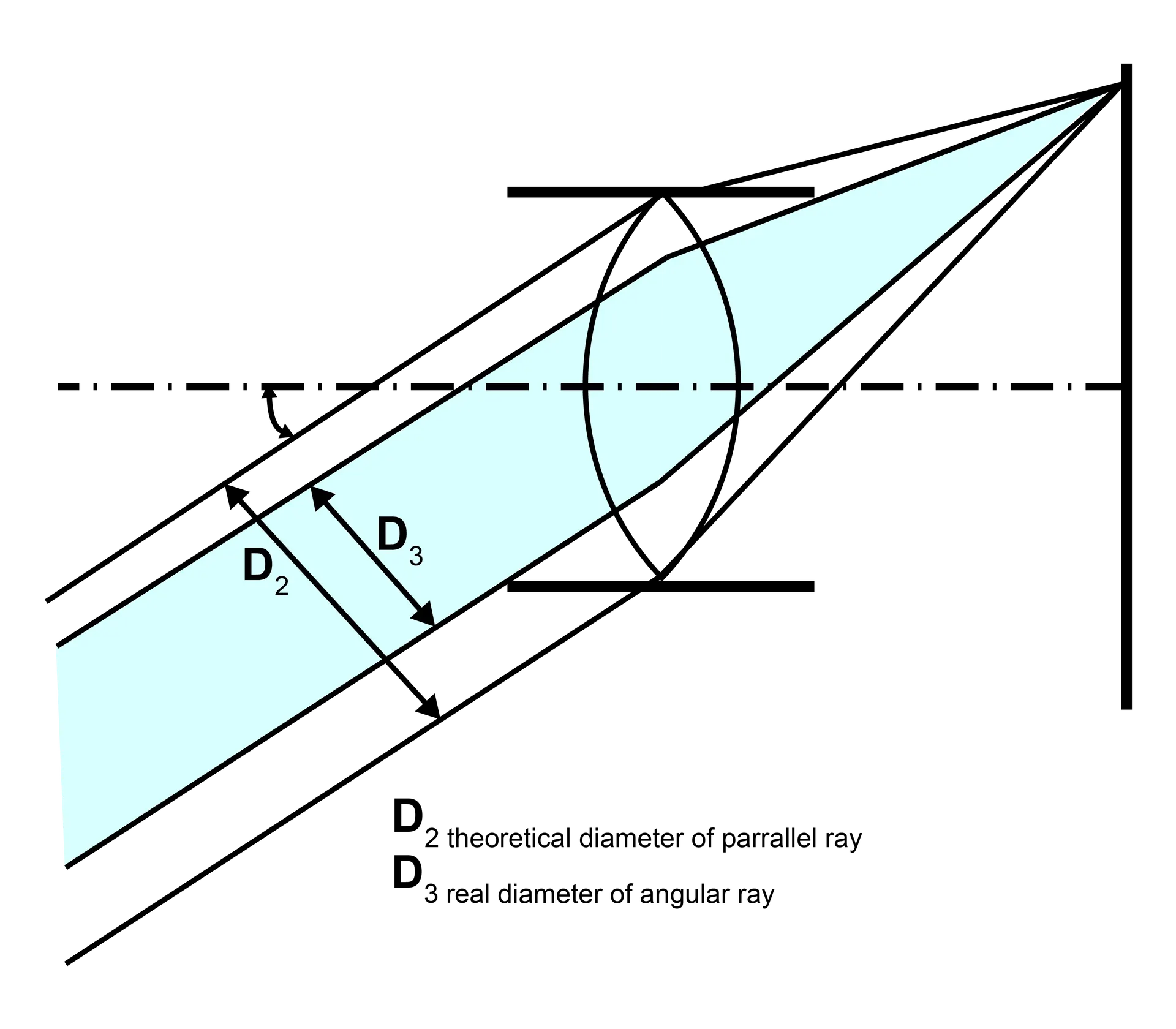
Figure 2: The explanation for mechanical shading.
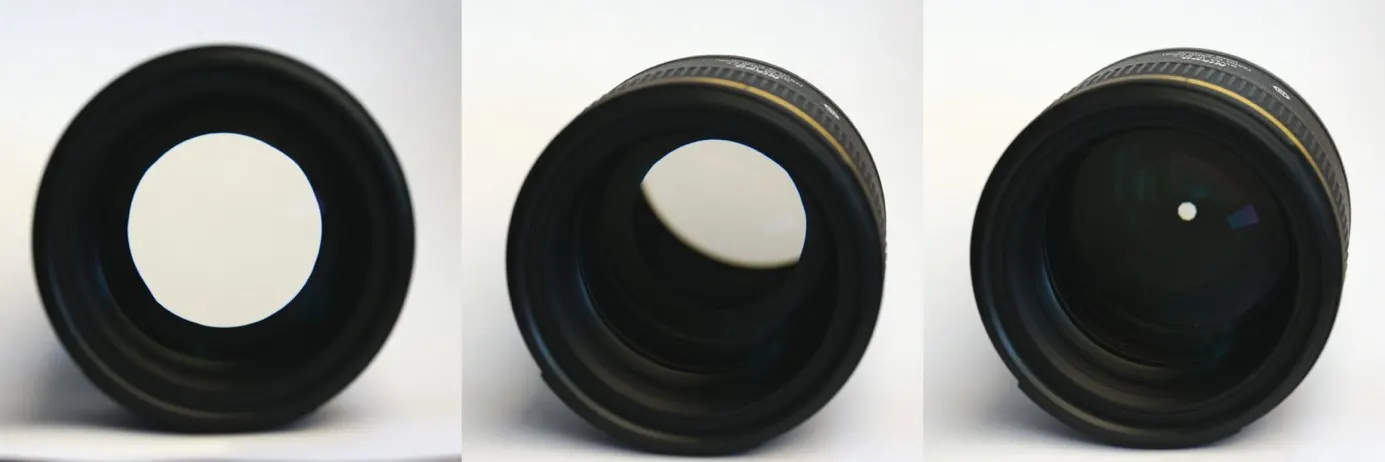
Image 2: Mechanical shading with an open and closed aperture.
Measuring luminance shading
When measuring luminance shading, ISO 17957 differentiates between the CIELAB method of "lightness non-uniformity" and the X, Y, Z method of "luminance non-uniformity" using two related formulas. The standard describes the measurement in detail.
Lightness shading:

Luminance shading:
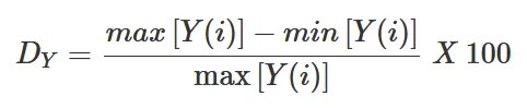
With the measurement results of luminance shading, a polynomial fit can be calculated and used to brighten the corners to compensate for the shading. Thus, compensating for a moderate shading level can be done in the camera imaging piper or during raw image processing.
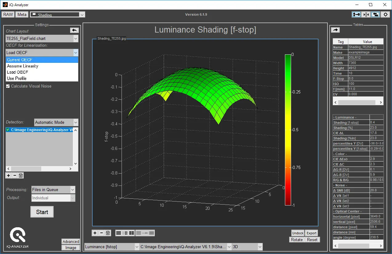
Image 3: Luminance shading measurement results from the iQ-Analyzer.
Color shading
Color shading (or color non-uniformity) usually describes a shift in color from the center of the image to the corners. This type of shading typically occurs in images captured with a camera with a smaller sensor. Color shading has multiple causes, including the two most common types, pixel crosstalk off-axis, and the IR-cut filter transmission.
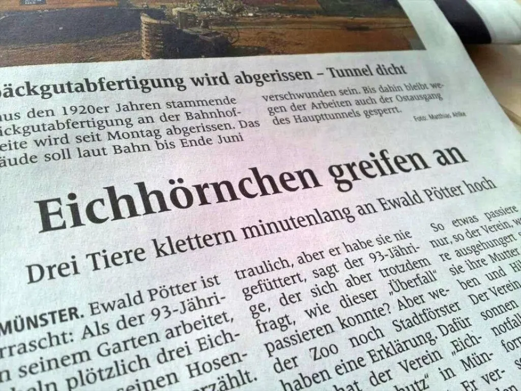
Image 4: A color shading example showing a magenta spot in the center with green corners.
Pixel crosstalk color shading
Pixel crosstalk off-axis describes an increase in the spatial variation between (crosstalk) the pixels. Lenses that are not designed as near telecentric can often experience pixel crosstalk shading.
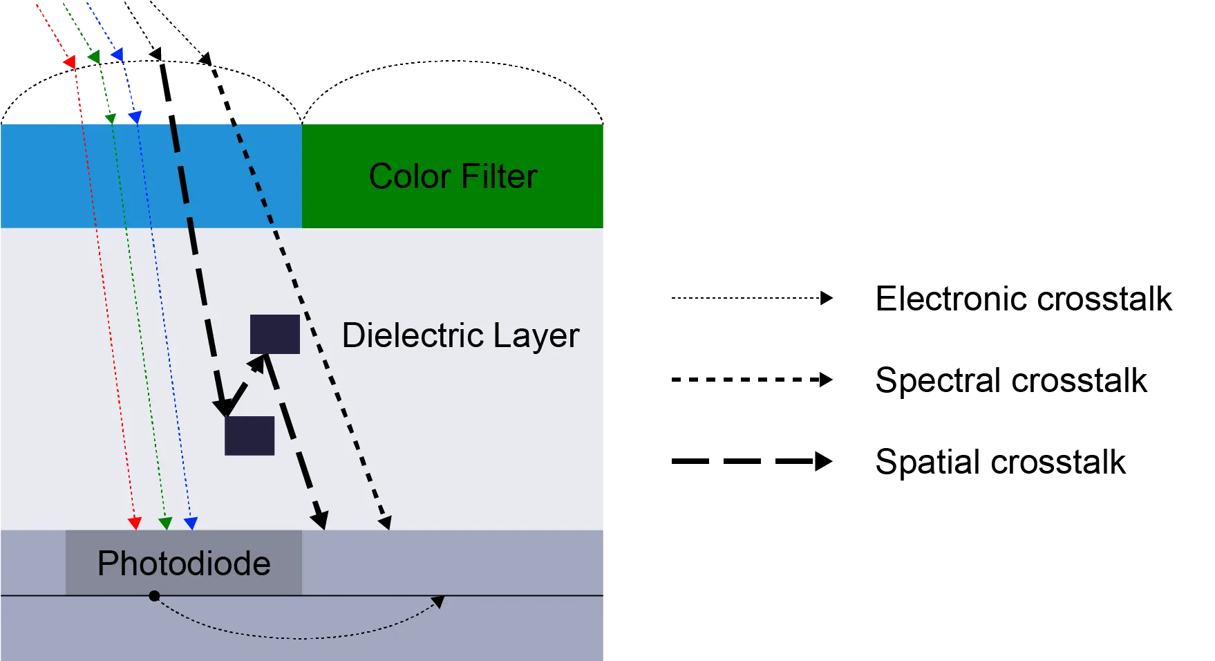
Image 5: Light collected by the sensor varies with the angle of incidence due to pixel crosstalk.
IR-cut filter
The transmission of the IR-cut filter shifts towards a shorter wavelength as the angle of incidence increases. The IR-cut filter shift has a more substantial impact on the image if the light source contains a lot of IR radiance like natural sunlight or incandescent lights. Fluorescent tubes or LEDs do not display this phenomenon as often due to the lag of the IR content in their spectrums.
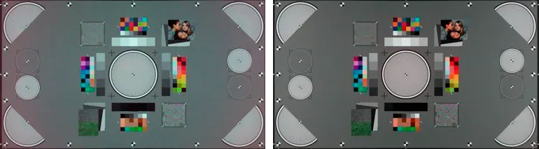
Image 7: The test chart image on the left was taken with a light source that matches the D55 spectrum (sunlight) and shows significant colour shading along the edges. The same test chart image on the right, captured with a D55-simulating fluorescent tube (no IR), does not show colour shading.
Measuring color shading
ISO 17957 outlines two separate formulas for measuring color shading. The first formula describes the chrominance non-uniformity and focuses on the differences in the a* and b* channels. The second formula details the total color non-uniformity, which takes into account the lightness L*.
Chrominance non-uniformity
An analysis of the chrominance non-uniformity is performed by first calculating the overall average (a*) ̅ and (b*) ̅ for the entire image using the block average values: a^* (i) and b^* (i).

m:number of measurement blocks
Calculate the chrominance deviation of the i block with the following formula.

The chrominance non-uniformity Dc is defined as the maximum deviation from the overall average of the following formula.

Total color non-uniformity
An analysis of total color non-uniformity begins by first calculating the overall maximums and minimums of L*(i), a*(i), and b*(i).
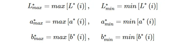
Calculate the total color non-uniformity DTotal by the following formula.

Conclusion
Shading describes a decrease in image brightness from the center to the corners or a variation of color over the imaging field that often occurs in cameras with a small sensor. Shading, therefore, influences image quality by creating unwanted dark or shaded edges.
When visualizing the shading of a camera system, it is easiest to capture a flat field image, a photograph of white paper with uniform illumination, or a photograph of a uniform diffuse light source such as the opening of an integrating sphere.
When we test for camera shading in our test lab, we closely follow the methods presented in ISO 17957. We have found that using a matt diffuser chart provides us with the best results for an overall evaluation of shading.
Need help testing Shading?
Find the right products and services for testing a camera system's Shading performance.
Products & Solutions
Test Charts
Analysis Software
Test Services
Get professional camera testing with our image quality test lab, one of the world's largest independent camera test labs.