Resolution and Sharpness Measurement
SFR, MTF and ISO 12233 explained for camera testing
Introduction
Image resolution is the ability of a digital camera to reproduce the details of a scene. Resolution is an essential image quality attribute as it relates to the overall image quality perceived by a human observer. Various factors influence image resolution including the lens quality, alignment of the components, ideal focusing, exposure time, a sensor with optical components in front of it, and aperture.
All of these components are responsible for reproducing the details of objects within a scene.
At a glance
Resolution vs. pixel count: resolution describes how much scene detail a camera reproduces. The pixel count only sets the upper limit.
SFR and MTF: the spatial frequency response (SFR) shows how well detail is reproduced, from 0 % to 100 %. The MTF is a special case of the SFR based on sinusoidal patterns.
ISO 12233: the international standard for resolution measurement of digital cameras, with the e-SFR and s-SFR methods.
e-SFR vs. s-SFR: slanted edges are compact and flexible but sensitive to sharpening. Sinusoidal Siemens stars are robust against image processing and work without RAW data.
Key metrics: MTF10 (limiting resolution), MTF50 and acutance.
Key Products & Solutions
When does insufficient resolution occur?
During the first years of digital photography, it was usually the sensor with its limited number of pixels that was the obstacle for image resolution. For this reason, the number of pixels is often wrongly referred to as resolution. With an increasing number of pixels, the barrier has shifted over the last few years to factors like optical performance, autofocus, and motion blur. Today's pixel size limits are frequently pushed to the point that the optical phenomenon diffraction is now a point of consideration.
Today, high resolution relies on a high-quality lens to produce fine detail, especially image quality in the image corner. As an image expands from the center to the corner, the resolution will often worsen due to various optical factors such as spherical and chromatic aberrations.
Methods for measuring resolution
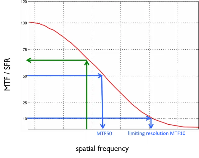
The measurement of resolution is a measurement of the spatial frequency response (SFR). This function describes how well the system under test can reproduce a range of spatial frequencies on a scale from 0% to 100%.
The third method to obtain an SFR is the dead leaves approach. This approach is highly optimized for a textureloss analysis. Details can be found in our article on texture loss.
e-SFR / Slanted edges
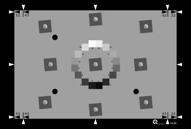
The fundamental idea of the slanted edge analysis goes back to scanner evaluation before digital cameras were widely available. The system under test had to be able to reproduce a slanted edge test target.
The main idea of an e-SFR measurement in three steps: 1. obtain the edge spread function, 2. obtain the line spread function, 3. obtain the spatial frequency response.
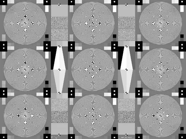
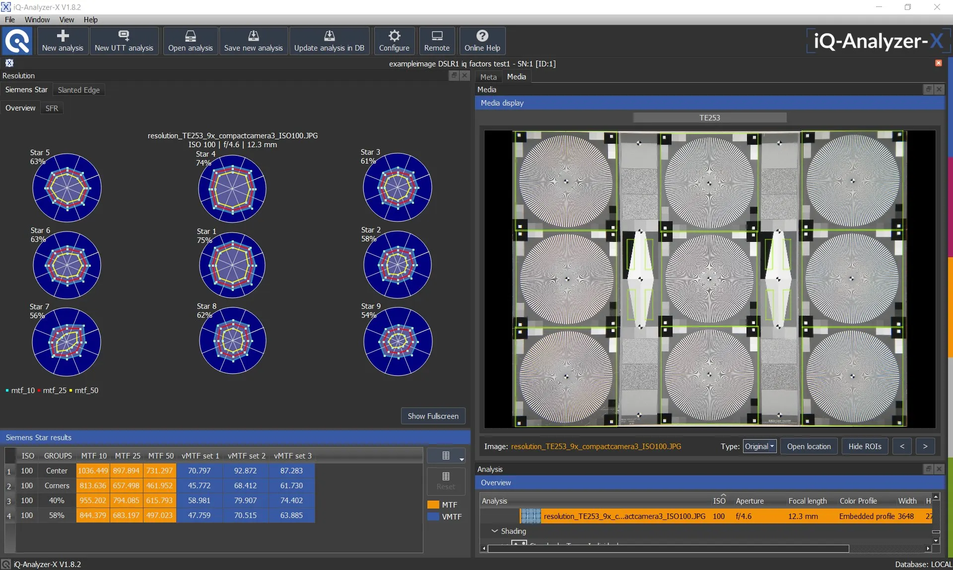
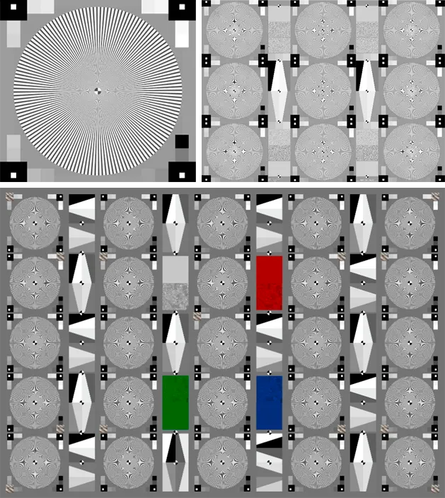
While the slanted edge method has been a part of ISO 12233 since the first version, the revision in 2014 has since added the s-SFR method. Although a recent addition to the standard, this method had already been in practical use for over ten years by our test lab and many customers had come to rely on it. The best test target for this procedure is a sinusoidal Siemens star (Figure 5). So, while it is true that a Siemens star is based on rectangular functions with increasing spatial frequency and decreasing radius, the sinusoidal Siemens star also utilizes harmonic functions.
The central concept is based on the fact that a harmonic function processed by a linear system will only be modified in modulation and/or phase but will remain harmonic. For a range of spatial frequencies, the ratio of the modulation in the image to the modulation in the target is measured. This ratio is the MTF of the system under test.
Modulation = (Imax − Imin) / (Imax + Imin)
What are the metrics derived from an SFR?
The limiting resolution is also known as MTF10, or the spatial frequency that leads to an SFR of 10%. The 10% limit has been determined based on the “Rayleigh criterion”, which describes the limit of resolution based on the diffraction pattern of two points.
The MTF10 value describes the absolute maximum of details that you can find in an image in practice. These details are shown with low contrast but are still visible.
As the limiting resolution represents the maximum performance, this does not correlate with the subjective impression of sharpness. For a long time, the assumption was that the MTF50 value would be a better description of an image's sharpness. MTF50, however, is the spatial frequency that leads to an SFR of 50%. There is a correlation between subjective sharpness and MTF50, but new metrics, also referred to as acutance, show a more thorough correlation.
The acutance is calculated based on the measured SFR and the contrast sensitivity function (CSF) of the human visual system. The CSF is a model of how a human observer perceives spatial frequencies. Thus, measured spatial frequencies from the image need to convert into a representation of spatial frequencies for a specific viewing condition. Other than MTF50, the acutance takes the human observer and the particular viewing condition into account.
Key terms
| H3 Key terms Term | Definition |
|---|---|
| SFR | Spatial frequency response: how well a camera reproduces detail across spatial frequencies, from 0 % to 100 %. |
| MTF | Modulation transfer function: an SFR measured with harmonic (sinusoidal) patterns. |
| MTF10 | Spatial frequency at which the SFR drops to 10 %. Describes the limiting resolution. |
| MTF50 | Spatial frequency at which the SFR drops to 50 %. Correlates with perceived sharpness. |
| Acutance | Sharpness metric combining the SFR with the contrast sensitivity of the human eye for a viewing condition. |
| LW/PH | Line widths per picture height: relates spatial frequency to the image height. |
Which method should you use?
The e-SFR approach is relatively simple and allows high flexibility in chart design. Another benefit is the complete SFR measurement that is done within a small area in the image. When using the e-SFR method, it is essential to remember that image enhancement algorithms positively influence signal processing. It is quite simple to detect edges and to enhance the contrast of these edges. Thus, e-SFR measurements are affected by certain factors such as sharpening. These factors will not be a problem if the RAW data of the camera is accessible.
The s-SFR approach is much more robust against sharpening and other image enhancement algorithms. It allows the measurement and assessment of a system's optical performance even when RAW data is unavailable. Other than e-SFR, the s-SFR is, in most cases, capable of providing reliable information within the high frequencies to obtain, for example, MTF10.
If no RAW data is available, it is most beneficial to measure different SFR on different structures. That way, we can get the optical performance from the s-SFR and information about sharpening from the e-SFR.
Conclusion
Resolution is one of the fundamental elements of image quality. Inadequate resolution leads to more than low-quality images; it can also lead to dangerous situations, especially in security and automotive industries that often rely on high-resolution images and video for safety and effectiveness. It is thus vital to properly test and analyze the image resolution of the camera system under test.
Frequently asked questions
References and further readings
About this article:
Written by the Image Engineering R & D team. Technical review: Uwe, Artman. Last updated: 2026 . Image Engineering is an independent test lab for camera image quality and the developer and manufacturer of the complete test infrastructure, including test charts, analysis software, and measurement equipment.